AWG Wire Stranding Charts: UL, Metric, & SAE
When choosing the right copper wire for your applications, understanding the various specifications, standards, and chart readings is crucial. This guide will walk you through the different types of wire strands, their conformities to various standards, and how these impact your project's requirements.
Solid & Stranded Specifications
-
Copper wires, both solid and stranded, come in various specifications that determine their suitability for different applications. They must conform to several standards and regulations to ensure safety, performance, and compatibility. The most common standards for copper wire include:
- ASTM B-1, B-2, and B-8: These standards cover hard-drawn, medium-drawn, soft or annealed copper wire, and concentric lay copper strands, respectively.
- Federal Standard QQ-W-343: Ensures uniformity in manufacturing and quality.
- National Bureau of Standards Handbook: Provides additional guidelines for wire and cable manufacturing.
- ASTM B-258: Governs the calculation of breaking strength and resistance for copper wires.
View this Page as a PDF >
Solid Bare Copper
Solid bare copper wires are widely used in electrical wiring due to their excellent conductivity, flexibility, and strength. Here are some specifications you need to know:
| Cross Sectional | Hard Drawn | Medium Hard Drawn | Soft Drawn | |||||||
|---|---|---|---|---|---|---|---|---|---|---|
| AWG | Nom.
Diameter (in) |
Area
(Cir. Mils) |
Appx.
Net Wt. (lb/1000ft) |
Min.
Breaking Strength (lb) |
Max.
DC Resistance @ 20C (OHMS/1000ft) |
Min.
Breaking Strength (lb) |
Max.
Breaking Strength (lb) |
Max DC
Resistance @ 20C (OHMS/1000ft) |
Max.
Breaking Strength (lb) |
Max. DC
Resistance @ 20C (OHMS/1000ft) |
| 36 | 0.0050 | 25.0 | 0.0757 | 1.4 | 431 | 1.2 | 1.3 | 429 | 0.78 | 415 |
| 35 | 0.0056 | 31.4 | 0.0949 | 1.8 | 344 | 1.5 | 1.6 | 342 | 0.99 | 331 |
| 34 | 0.0063 | 39.7 | 0.120 | 2.2 | 272 | 1.8 | 2.0 | 270 | 1.2 | 261 |
| 33 | 0.0071 | 50.4 | 0.153 | 2.8 | 214 | 2.3 | 2.6 | 213 | 1.6 | 206 |
| 32 | 0.0080 | 64.0 | 0.194 | 3.5 | 168 | 2.9 | 3.2 | 168 | 1.9 | 162 |
| 31 | 0.0089 | 79.2 | 0.240 | 4.4 | 136 | 3.6 | 4.0 | 135 | 2.5 | 131 |
| 30 | 0.0100 | 100 | 0.303 | 6 | 108 | 4.5 | 5.1 | 107 | 3.2 | 104 |
| 29 | 0.0113 | 128 | 0.387 | 7 | 84.5 | 5.6 | 6.3 | 84.0 | 3.9 | 81.2 |
| 28 | 0.0126 | 159 | 0.481 | 9 | 67.9 | 7.1 | 7.9 | 67.6 | 5.0 | 65.3 |
| 27 | 0.0142 | 202 | 0.610 | 11 | 53.5 | 8.9 | 10 | 53.2 | 6.3 | 51.4 |
| 26 | 0.0159 | 253 | 0.765 | 14 | 42.7 | 11 | 13 | 42.4 | 7.9 | 41.0 |
| 25 | 0.0179 | 320 | 0.970 | 17 | 33.7 | 14 | 16 | 33.5 | 10 | 32.4 |
| 24 | 0.0201 | 404 | 1.22 | 22 | 26.7 | 17 | 20 | 26.6 | 13 | 25.7 |
| 23 | 0.0226 | 511 | 1.55 | 27 | 21.1 | 22 | 25 | 21.0 | 15 | 20.3 |
| 22 | 0.0253 | 640 | 1.94 | 34 | 16.9 | 27 | 31 | 16.8 | 19 | 16.2 |
| 21 | 0.0285 | 812 | 2.46 | 43 | 13.3 | 34 | 39 | 13.2 | 24 | 12.8 |
| 20 | 0.0320 | 1,020 | 3.10 | 54 | 10.5 | 43 | 49 | 10.5 | 31 | 10.1 |
| 19 | 0.0359 | 1,290 | 3.90 | 68 | 8.37 | 54 | 61 | 8.32 | 39 | 8.05 |
| 18 | 0.0403 | 1,620 | 4.92 | 85 | 6.64 | 67 | 76 | 6.61 | 49 | 6.39 |
| 17 | 0.0453 | 2,050 | 6.21 | 108 | 5.26 | 84 | 96 | 5.23 | 62 | 5.05 |
| 16 | 0.0508 | 2,580 | 7.81 | 135 | 4.18 | 106 | 120 | 4.16 | 73 | 4.02 |
| 15 | 0.0571 | 3,260 | 9.87 | 170 | 3.31 | 151 | 165 | 3.29 | 99 | 3.18 |
| 14 | 0.0641 | 4,110 | 12.4 | 214 | 2.63 | 167 | 189 | 2.61 | 124 | 2.52 |
| 13 | 0.0720 | 5,180 | 15.7 | 268 | 2.09 | 209 | 237 | 2.07 | 157 | 2.00 |
| 12 | 0.0808 | 6,530 | 19.8 | 337 | 1.65 | 262 | 297 | 1.64 | 197 | 1.59 |
| 11 | 0.0907 | 8,230 | 24.9 | 423 | 1.31 | 327 | 372 | 1.30 | 249 | 1.26 |
| 10 | 0.1019 | 10,380 | 31.43 | 529 | 1.039 | 410 | 467 | 1.033 | 314 | 0.9988 |
| 9 | 0.1144 | 13,090 | 39.62 | 660 | 0.8241 | 513 | 585 | 0.8199 | 380 | 0.7925 |
| 8 | 0.1285 | 16,510 | 49.98 | 826 | 0.6532 | 644 | 734 | 0.6498 | 479 | 0.6281 |
| 7 | 0.1443 | 20,820 | 63.03 | 1030 | 0.5180 | 806 | 921 | 0.5153 | 605 | 0.4981 |
| 6 | 0.1620 | 26,240 | 79.44 | 1280 | 0.4110 | 1010 | 1154 | 0.4088 | 762 | 0.3952 |
| 5 | 0.1819 | 33,090 | 100.2 | 1591 | 0.3258 | 1265 | 1446 | 0.3243 | 961 | 0.3134 |
| 4 | 0.2043 | 41,740 | 126.3 | 1970 | 0.2584 | 1584 | 1814 | 0.2571 | 1213 | 0.2485 |
| 3 | 0.2294 | 52,620 | 159.3 | 2439 | 0.2049 | 1984 | 2273 | 0.2039 | 1529 | 0.1971 |
| 2 | 0.2576 | 66,360 | 200.9 | 3002 | 0.1625 | 2450 | 2814 | 0.1617 | 1928 | 0.1563 |
| 1 | 0.2893 | 83,690 | 253.3 | 3688 | 0.1289 | 3024 | 3484 | 0.1282 | 2432 | 0.1239 |
| 1/0 | 0.3249 | 105,600 | 319.5 | 4518 | 0.1011 | 3731 | 4311 | 0.1016 | 2985 | 0.09825 |
| 2/0 | 0.3650 | 133,100 | 403 | 5519 | 0.0802 | 4600 | 5330 | 0.0798 | 3763 | 0.0779 |
| 3/0 | 0.4100 | 167,800 | 508 | 6720 | 0.0636 | 5666 | 6590 | 0.0633 | 4745 | 0.0618 |
| 4/0 | 0.4600 | 211,600 | 640 | 8143 | 0.0505 | 6980 | 8143 | 0.0502 | 5983 | 0.0490 |
The above table represents various properties of solid bare copper wires, including their diameter, cross-sectional area, weight, and breaking strength. Each attribute plays a critical role in determining the wire's suitability for different applications, from residential wiring to industrial applications.
Stranded Bare Copper
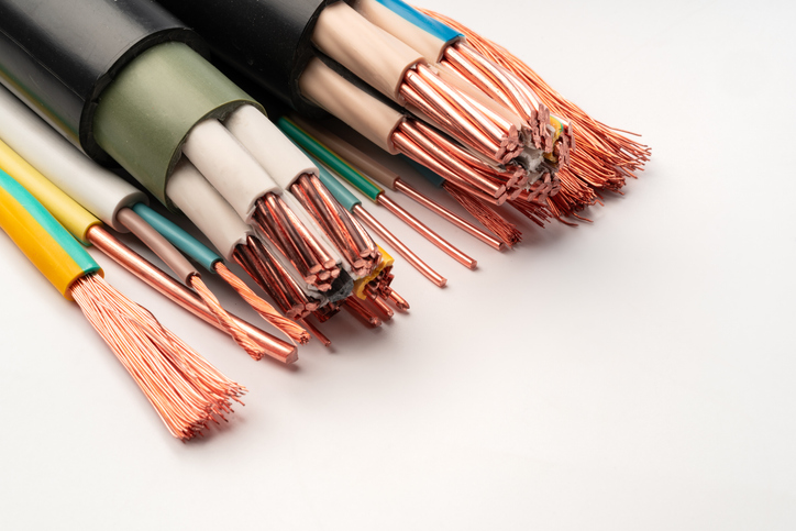
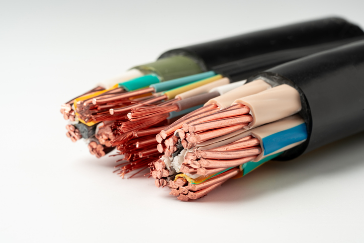
Stranded bare copper wire consists of multiple copper strands twisted together, providing better flexibility compared to solid wires. The following table outlines key characteristics:
| Size (AWG/MCM) | Stranding | Nominal OD of Strand | Approx. OD (in) | Weight (lbs/Mft) | OHMS/Resistance (per Mft) |
|---|---|---|---|---|---|
|
36 34 |
7/44 7/42 |
0.0020 0.0025 |
0.0060 0.0075 |
0.085 0.132 |
382.0 244.0 |
| 32 |
7/40 19/44 |
0.0031 0.0020 |
0.0094 0.0099 |
0.203 0.230 |
159.0 142.0 |
| 30 |
7/38 19/42 |
0.0040 0.0025 |
0.0120 0.0120 |
0.339 0.359 |
95.40 90.80 |
| 28 |
7/36 19/40 |
0.0050 0.0031 |
0.0150 0.0160 |
0.529 0.553 |
61.00 59.10 |
| 26 |
7/34 10/36 19/38 |
0.0063 0.0050 0.0040 |
0.0190 0.0190 0.0200 |
0.841 0.757 0.920 |
38.50 40.40 35.50 |
| 24 |
7/32 10/34 19/36 41/40 |
0.0080 0.0063 0.0050 0.0031 |
0.0240 0.0230 0.0240 0.0240 |
1.356 1.201 1.430 1.160 |
23.30 26.09 22.70 25.59 |
| 22 |
7/30 19/34 26/36 |
0.0100 0.0063 0.0050 |
0.0300 0.0310 0.0300 |
2.120 2.280 1.970 |
15.30 14.30 15.94 |
| 20 |
7/28 10/30 19/32 26/34 41/36 105/40 |
0.0126 0.0100 0.0080 0.0063 0.0050 0.0032 |
0.0380 0.0410 0.0400 0.0370 0.0370 0.0400 |
3.150 3.090 3.680 3.120 3.100 3.200 |
9.600 10.168 8.900 10.05 10.02 10.609 |
| 18 |
7/26 16/30 19/0.0092 41/34 65/36 168/40 |
0.0159 0.0100 0.0092 0.0063 0.0050 0.0032 |
0.0480 0.0520 0.0450 0.0470 0.0460 0.0520 |
5.360 4.940 4.900 4.920 4.910 5.140 |
6.040 6.740 6.323 6.600 6.390 6.631 |
| 17 | 210/40 | 0.0032 | 0.0590 | 6.400 | 5.304 |
| 16 |
7/24 19/0.0117 19/29 26/30 65/34 105/36 |
0.0201 0.0117 0.0113 0.0100 0.0063 0.0050 |
0.0600 0.0560 0.0570 0.0660 0.0600 0.0600 |
8.560 8.020 7.350 8.030 7.810 7.950 |
3.670 4.152 4.480 4.000 4.020 3.990 |
| 14 |
7/0.0242 7/22 19/27 19/0.0147 41/30 105/34 |
0.0242 0.0253 0.0142 0.0147 0.0100 0.0063 |
0.0726 0.0760 0.0710 0.0700 0.0700 0.0740 |
12.76 13.56 11.59 12.70 12.40 12.61 |
2.480 2.310 2.700 2.476 2.660 2.490 |
| 12 |
7/20 19/25 19/0.0185 65/30 165/34 |
0.0320 0.0179 0.0185 0.0100 0.0063 |
0.0960 0.0900 0.0925 0.0910 0.0950 |
21.69 18.43 20.15 19.66 19.82 |
1.450 1.770 1.564 1.680 1.580 |
| 10 |
7/0.0385 19/0.0234 37/26 49/27 105/30 |
0.0385 0.0234 0.0159 0.0142 0.0100 |
0.1160 0.1170 0.1100 0.1200 0.1140 |
32.06 32.06 28.31 29.89 31.76 |
1.000 1.000 1.160 1.280 0.980 |
| 8 |
7/0.0486 19/0.0295 54/25 84/27 133/29 168/30 420/34 |
0.0486 0.0295 0.0179 0.0142 0.0113 0.0100 0.0063 |
0.1460 0.1440 0.1506 0.1490 0.1670 0.1740 0.1620 |
50.10 50.00 55.00 52.00 54.00 53.10 53.00 |
0.650 0.650 0.624 0.638 0.640 0.660 0.680 |
| 6 |
7/0.0612 19/0.0372 133/27 266/30 665/34 |
0.0612 0.0372 0.0142 0.0100 0.0063 |
0.1840 0.1860 0.2100 0.2040 0.2150 |
81.10 81.10 84.10 83.20 84.00 |
0.410 0.400 0.410 0.417 0.400 |
| 4 |
7/0.0772 19/0.0469 133/25 420/30 1064/34 |
0.0772 0.0469 0.0179 0.0100 0.0063 |
0.2320 0.2350 0.2570 0.2570 0.2690 |
129.00 129.00 135.00 140.00 134.00 |
0.260 0.240 0.258 0.264 0.266 |
| 2 |
7/0.0974 19/0.0591 133/0.0223 665/30 1666/34 |
0.0974 0.0591 0.0223 0.0100 0.0063 |
0.2920 0.2920 0.3290 0.3380 0.3370 |
204.90 205.00 208.00 213.00 212.00 |
0.162 0.170 0.166 0.167 0.169 |
| 1 |
19/0.0664 133/0.0251 259/0.0180 836/30 2107/34 |
0.0664 0.0251 0.0180 0.0010 0.0063 |
0.3320 0.3800 0.3780 0.3650 0.3760 |
266.00 264.00 265.24 266.00 268.00 |
0.130 0.132 0.121 0.133 0.134 |
| 1/0 |
7/0.01228 19/0.0745 37/0.0534 259/24 1064/30 2646/34 |
0.1228 0.0745 0.0534 0.0201 0.0010 0.0063 |
0.3690 0.3730 0.3700 0.4240 0.4510 0.4370 |
326.00 326.00 326.00 331.00 338.00 337.00 |
0.102 0.100 0.102 0.105 0.105 0.106 |
| 2/0 |
7/0.1379 19/0.0837 37/0.0600 259/0.0227 1330/30 3325/34 |
0.1379 0.0837 0.0600 0.0227 0.0100 0.0063 |
0.4140 0.4190 0.4200 0.4560 0.4960 0.5340 |
410.90 410.90 411.00 430.00 430.00 427.00 |
0.081 0.081 0.080 0.083 0.084 0.085 |
| 3/0 |
7/0.1548 19/0.0940 37/0.0673 259/0.0255 1666/30 4256/34 |
0.1548 0.0940 0.0673 0.0255 0.0100 0.0063 |
0.4650 0.4700 0.4700 0.5360 0.5330 0.6150 |
518.00 518.00 518.00 533.00 676.00 547.00 |
0.064 0.064 0.065 0.066 0.067 0.0647 |
| 4/0 |
7/0.1739 19/0.1055 37/0.0756 259/0.0286 427/0.0223 2107/30 5320/34 |
0.1739 0.1055 0.0756 0.0286 0.0223 0.0100 0.0063 |
0.5220 0.5280 0.5290 0.6010 0.6020 0.6700 0.6450 |
653.00 653.00 653.00 671.22 676.00 674.00 684.00 |
0.0510 0.0510 0.048 0.048 0.0522 0.0530 0.0535 |
| 250MCM |
19/0.1147 37/0.0822 |
0.1147 0.0822 |
0.5750 0.5750 |
771.00 771.00 |
0.0430 0.0430 |
| 350MCM |
19/0.1357 37/0.0973 |
0.1357 0.0973 |
0.6810 0.6810 |
1081.0 1081.0 |
0.030 0.031 |
| 500MCM |
19/0.1622 37/0.1162 |
0.1622 0.1162 |
0.8130 0.8130 |
1544.0 1544.0 |
0.022 0.022 |
| 750MCM | 61/0.1109 | 0.1109 | 0.9980 | 2316.0 | 0.010 |
| 1000MCM | 61/0.1280 | 0.1280 | 1.1520 | 3088.0 | 0.009 |
AWG to mm2
| AWG | mm2 | AWG | mm2 | AWG | mm2 | AWG | mm2 | AWG | mm2 | AWG | mm2 |
|---|---|---|---|---|---|---|---|---|---|---|---|
| 30 | 0.05 | 21 | 0.38 | 14 | 2.5 | 4 | 25 | 3/0 | 95 | 600MCM | 300 |
| 28 | 0.08 | 20 | 0.50 | 12 | 4 | 2 | 35 | 4/0 | 120 | 750MCM | 400 |
| 26 | 0.14 | 18 | 0.75 | 10 | 6 | 1 | 50 | 300MCM | 150 | 1000MCM | 500 |
| 24 | 0.25 | 17 | 1.0 | 8 | 10 | 1/0 | 55 | 350MCM | 185 | ||
| 22 | 0.34 | 16 | 1.5 | 6 | 16 | 2/0 | 70 | 500MCM | 240 |
Automotive SAE Recommended Conductors
| AWG | Number of Strands | Nominal OD of Strand |
|---|---|---|
| 22 | 7/30 | 0.0100 |
| 20 | 7/28 | 0.0126 |
| 18 | 16/30 | 0.0100 |
| 18 | 19/32 | 0.0080 |
| 16 | 19/29 | 0.0113 |
| 14 | 19/27 | 0.0142 |
| 12 | 19/25 | 0.0179 |
| 10 | 19/23 | 0.0226 |
| 8 | 19/21 | 0.0285 |
| 6 | 37/21 | 0.0285 |
| 6 | 133/27 | 0.0142 |
| 4 | 61/22 | 0.0253 |
| 4 | 133/25 | 0.0179 |
| 2 | 133/23 | 0.0218 |
| 1 | 133/22 | 0.0243 |
| 1/0 | 133/21 | 0.0275 |
| 2/0 | 133/20 | 0.0309 |
| 3/0 | 266/22 | 0.0249 |
| 4/0 | 418/23 | 0.0226 |
Key Differences Between Solid and Stranded Copper Wires
Both solid and stranded copper wires have their advantages:
- Solid Copper Wire: Offers high tensile strength and is ideal for long, straight runs with minimal bending.
- Stranded Copper Wire: Provides flexibility, making it suitable for applications that require bending or movement, such as in portable tools, appliances, and automotive industries.
Selecting the Right Copper Wire for Your Needs
Choosing between solid and stranded copper wires depends on factors like:
- Application: Solid wires are better for permanent installations, while stranded wires are preferable for applications where flexibility is needed.
- Environment: Stranded wires are more suitable in environments where vibrations and movements are frequent.
- Current Load: Consider the wire's gauge, breaking strength, and resistance to handle the expected electrical load safely.
Wire Stranding Impact on Electrical Performance
Choosing the right wire stranding affects several aspects of electrical performance. When selecting wire for your application, consider the following factors that stranding impacts:
- Conductivity: Stranded wires have slightly lower conductivity due to air gaps between strands, which can affect performance in high-current applications.
- Resistance: Stranded wires generally have higher resistance than solid wires, which can cause voltage drops over long distances.
- Current-Carrying Capacity (Ampacity): Stranded wires have similar ampacity to solid wires, but proper sizing is essential to prevent overheating.
- Heat Dissipation: Stranded wire dissipates heat more effectively due to its increased surface area, making it suitable for high-current applications.
- Flexibility and Vibration Resistance: Stranded wires are more flexible and durable in environments with frequent movement or vibration.
- Voltage Drop Considerations: Longer cable runs using stranded wire may experience voltage drops, so proper gauge selection is important to maintain performance.
Related Resources

How to Choose the Right Wire or Cable
In selecting a wire or cable for an application, several factors should be considered. Learn More
Selecting a Conductor
Even in the design of a simple single insulated wire many factors must be considered, including physical properties of the conductorLearn More
Types of Strand Construction
Strand construction in wire and cable is crucial because it directly affects flexibility, durability, and electrical performance, impacting the overall reliability and efficiency of the cable in various applications.Learn More


