Cable Installation Guidelines
Flexible Cable Installation Guidelines
Care must be taken with any flexing application during the installation of the cable. Here are a few guidelines to help prevent kinking:
- Cable should be pre-cut and hung suspended for 48 hours to develop its most natural set and lay prior to installation.
- Cable should be installed with, not against, its natural set.*
- Strain relief on either end will reduce conductor breakage at the flex points.
- If there are any kinks in the cable when it is installed, it will always remain and eventually cause a cable failure.
- After installation, the most critical factors in the cable are minimum bend radius and reel tension.
*The natural set occurs during the manufacturing of the cable. The cable is cured in one direction on the reel with a definite difference in its ability to be flexed on way as opposed to another.
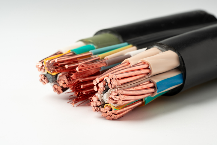
There are a variety of multi-conductor cables designed for many types of applications. Multi-conductor cables consist of two or more conductors primarily used for control or power applications.
One of the toughest applications for any multi-conductor cable is repeated handling by guide equipment in a forced direction. Examples of such applications include:
- Fork Trucks
- Power Track Systems
- Random Cable Reelers
- Festooning Systems
- Outdoor Trailing
These applications consist of moderate tension and repeated forced directional flexing or reeling. For these types of applications, best results can be obtained by using specially designed flex cables. Improper installation of flex cables, however, can result in premature cable failure.
When using specially designed flex cables, there are five criteria that must be considered:
- Bending Radii
- Cable Tension
- Operation Speed
- Temperature
- Ampacity
Bending Radii
The following table provides details relating to minimum bending radii which are recommended by the ICEA standards. These values are intended to optimize cable life. Reduced bending radii result in reduced cable life due to increased stress on the copper conductors and overall distortion of the cable. Therefore, reduced radii should only be considered for applications in which other factors, such as reduced cable tension, lower operation speed and ambient temperature are more favorable to cable life, or where the mechanical limitations of the installation do not allow the optimum radius.
Testing on various flex cables has shown that doubling the minimum bending radius for reeling applications can triple cable life at the maximum recommended tension. Therefore, the largest possible bending radius should be used to increase cable life.
| Minimum Bend Radius | |||
|---|---|---|---|
| Cable Type |
Fixed Installation |
Moderate Flex |
Cable Tracks |
| Unshielded Cables | 4 x Cable Diameter | 6 x Cable Diameter | 8 x Cable Diameter |
| Shielded Cables | 4 x Cable Diameter | 8 x Cable Diameter | 12 x Cable Diameter |
Cable Tension
Cable tension plays an extremely important role in determining cable life in reeling. The copper conductors are the principle strength member in flexible cable constructions. Even if you have good strain relief fittings on the cable, this will not minimize the fact that most of the tension will be supported by the copper conductors.
The effects of tension on a cable are dependent upon the pounds per cross-sectional area of the copper conductors. In other words, larger AWG wires and or more conductors can handle more tension than smaller AWG wires or fewer conductors.
The chart below is an example of how to help prevent cable from being overstressed. The values are calculated from the formula:
MCT = Maximum Continuous Tension
CMA = Conductor Circular Mil Area
Ch = Number of Conductors in Cable
| Cable Size | MCT (lbs.) |
|---|---|
| 6/C # 18 | 22 |
| 12/C #18 | 44 |
| 6/C #16 | 35 |
| 12/C #16 | 47 |
| 6/C #14 | 56 |
| 12/C #14 | 113 |
| 6/C #12 | 89 |
| 12/C #12 | 179 |
| CMA of Conductors |
|---|
| #18 AWG 19str = 1608 |
| #16 AWG 26str = 2600 |
| #14 AWG 41str = 4100 |
| #12 AWG 65str = 6500 |
Reeling Speed, Temperature & Ampacity
- Reeling speed and temperature are not as controllable as drum size and tension.
- If the reeling speed and/or temperature are extreme in any other way, considerations must be applied. In cold weather applications a larger drum diameter must be used whereas a high temperature may prescribe a larger AWG size to reduce inner conductor temperature.
- Predominantly, slow reeling speed and/or warmer temperatures, increase cable life.
- Cable speed normally should not exceed 400 feet per minute.
Power Track Installation
When selecting cable for power track, the following criteria should also be taken into consideration:
- Environmental conditions
- Temperature
- Chemical influences
- Indoor or outdoor operation
The cable should never be pulled from a coil or reel and inserted directly in the power track.
Cables should never be fixed to the track or tied together, and should always be installed parallel to each other with have sufficient length to allow full movement of the cable while the power track is in motion.
The weight of the cable should be evenly distributed. Heavier cables should be placed towards the outside power track and lighter ones positioned in the center.
After the cable is installed, the cables should be cycled through several flexes and watched to make sure they have freedom of movement. It is important to ensure that the cable can move freely within the bend radius so that movement of the cables within the track is possible.
Flat cables may be stacked in the power track prior to attachment with lightly tightened cable ties.
Related Resources

Application & Selection Guide for Standard Product
Read more on the typical applications for standard wire and cable products.Read More
DeReeling Procedures
In order that cables may run straight, special care should be taken not to twist the cable during handling.Learn More
What is a Wire?
Wire refers to a single, usually cylindrical, strand or rod of metal which is used to carry electricity and telecommunications signals. Learn More


